
[et_pb_section fb_built=”1″ _builder_version=”4.16″ global_colors_info=”{}”][et_pb_row _builder_version=”4.16″ background_size=”initial” background_position=”top_left” background_repeat=”repeat” global_colors_info=”{}”][et_pb_column type=”4_4″ _builder_version=”4.16″ custom_padding=”|||” global_colors_info=”{}” custom_padding__hover=”|||”][et_pb_text _builder_version=”4.16″ global_colors_info=”{}”]
[/et_pb_text][et_pb_divider show_divider=”off” _builder_version=”4.16″ height=”60px” global_colors_info=”{}”][/et_pb_divider][/et_pb_column][/et_pb_row][et_pb_row _builder_version=”4.16″ background_size=”initial” background_position=”top_left” background_repeat=”repeat” global_colors_info=”{}”][et_pb_column type=”4_4″ _builder_version=”4.16″ custom_padding=”|||” global_colors_info=”{}” custom_padding__hover=”|||”][et_pb_text admin_label=”Boron Nitride Nanotube Reinforced Metal Matrix Composites” _builder_version=”4.16″ global_colors_info=”{}”]
Boron Nitride Nanotube Reinforced Metal Matrix Composites
[/et_pb_text][/et_pb_column][/et_pb_row][et_pb_row _builder_version=”4.16″ background_size=”initial” background_position=”top_left” background_repeat=”repeat” global_colors_info=”{}”][et_pb_column type=”4_4″ _builder_version=”4.16″ custom_padding=”|||” global_colors_info=”{}” custom_padding__hover=”|||”][et_pb_text _builder_version=”4.16″ global_colors_info=”{}”]
[/et_pb_text][/et_pb_column][/et_pb_row][et_pb_row column_structure=”1_2,1_4,1_4″ _builder_version=”4.16″ background_size=”initial” background_position=”top_left” background_repeat=”repeat” global_colors_info=”{}”][et_pb_column type=”1_2″ _builder_version=”4.16″ custom_padding=”|||” global_colors_info=”{}” custom_padding__hover=”|||”][et_pb_text admin_label=”Boron Nitride Nanotube (BNNT) ” _builder_version=”4.16″ z_index_tablet=”500″ border_style_all=”none” border_width_top=”25″ border_width_right=”25″ border_width_bottom=”25″ border_width_left=”25″ global_colors_info=”{}”]
Boron Nitride Nanotube (BNNT) displays remarkable mechanical properties (elastic modulus and tensile strength exceeding 1 TPa and 60 GPa, respectively) and brilliant thermal endurance (capable of withstanding temperatures as high as 700-900°C without degrading or oxidizing). This makes BNNT an ideal reinforcement candidate for developing strong and lightweight nanocomposites. This research seeks to integrate BNNT in Aluminum, Magnesium and Titanium matrices to enhance their mechanical properties. Spark plasma sintering and solidification processes (casting, ultrasonic cavitation and plasma spray) are being adopted. In-situ mechanical techniques are being employed for real-time examination of strengthening mechanisms in these nanocomposites.
[/et_pb_text][/et_pb_column][et_pb_column type=”1_4″ _builder_version=”4.16″ custom_padding=”|||” global_colors_info=”{}” custom_padding__hover=”|||”][et_pb_blurb image=”https://pfl.fiu.edu/wp-content/uploads/BNNTcracks.jpg” admin_label=”Directionally Aligned Nanotubes Acting as Crack Bridges in Al-BNNT Composite” _builder_version=”4.16″ header_font_size=”8″ body_font_size=”8″ global_colors_info=”{}”]
Directionally Aligned Nanotubes Acting as Crack Bridges in Al-BNNT Composite
[/et_pb_blurb][/et_pb_column][et_pb_column type=”1_4″ _builder_version=”4.16″ custom_padding=”|||” global_colors_info=”{}” custom_padding__hover=”|||”][et_pb_blurb image=”https://pfl.fiu.edu/wp-content/uploads/BNNT-Wetting-and-Filling.jpg” admin_label=”Wetting and Filling of Nanotubes by Molten Aluminum during Equilibrium Solidification” _builder_version=”4.16″ body_font_size=”8″ global_colors_info=”{}”]
Wetting and Filling of Nanotubes by Molten Aluminum during Equilibrium Solidification
[/et_pb_blurb][/et_pb_column][/et_pb_row][et_pb_row _builder_version=”4.16″ background_size=”initial” background_position=”top_left” background_repeat=”repeat” global_colors_info=”{}”][et_pb_column type=”4_4″ _builder_version=”4.16″ custom_padding=”|||” global_colors_info=”{}” custom_padding__hover=”|||”][et_pb_text _builder_version=”4.16″ global_colors_info=”{}”]
[/et_pb_text][et_pb_divider show_divider=”off” _builder_version=”4.16″ height=”60px” global_colors_info=”{}”][/et_pb_divider][/et_pb_column][/et_pb_row][et_pb_row _builder_version=”4.16″ background_size=”initial” background_position=”top_left” background_repeat=”repeat” global_colors_info=”{}”][et_pb_column type=”4_4″ _builder_version=”4.16″ custom_padding=”|||” global_colors_info=”{}” custom_padding__hover=”|||”][et_pb_text admin_label=”Splat Sliding in Cold Sprayed Metallic Coatings” _builder_version=”4.16″ global_colors_info=”{}”]
Splat Sliding in Cold Sprayed Metallic Coatings
[/et_pb_text][/et_pb_column][/et_pb_row][et_pb_row column_structure=”1_2,1_4,1_4″ _builder_version=”4.16″ background_size=”initial” background_position=”top_left” background_repeat=”repeat” global_colors_info=”{}”][et_pb_column type=”1_2″ _builder_version=”4.16″ custom_padding=”|||” global_colors_info=”{}” custom_padding__hover=”|||”][et_pb_text admin_label=”Splat Sliding in Cold Sprayed Metallic Coatings” _builder_version=”4.16″ z_index_tablet=”500″ border_style_all=”none” border_width_top=”25″ border_width_right=”25″ border_width_bottom=”25″ border_width_left=”25″ global_colors_info=”{}”]
Cold sprayed coatings are composed of splats as their building blocks. Relative sliding between the splats can lead to deterioration of mechanical properties. This project seeks to examine the splat sliding behavior by in-situ mechanical investigations under a scanning electron microscope for real time visualization of deformation behavior. The splat sliding behavior is dependent on splat geometry, porosity, oxide content and inter-splat bonding. This project aims to establish correlation between processing conditions, coating microstructure and mechanical properties, and to understand the role of post-processing heat-treatment on arresting the splat sliding. In-situ techniques such as flexural tests, nanoindentation and nanoscratch in conjunction with Digital Image Correlation (DIC) analysis approach are adopted for visualizing the deformation mechanisms in cold sprayed microstructure.
[/et_pb_text][/et_pb_column][et_pb_column type=”1_4″ _builder_version=”4.16″ custom_padding=”|||” global_colors_info=”{}” custom_padding__hover=”|||”][et_pb_blurb image=”https://pfl.fiu.edu/wp-content/uploads/DIC-map-Cold-Spray.jpg” admin_label=”Microstructural strains determined by in-situ testing inside electron microscope” _builder_version=”4.16″ header_font_size=”8″ body_font_size=”8″ global_colors_info=”{}”]
Microstructural strains determined by in-situ testing inside electron microscope
[/et_pb_blurb][/et_pb_column][et_pb_column type=”1_4″ _builder_version=”4.16″ custom_padding=”|||” global_colors_info=”{}” custom_padding__hover=”|||”][et_pb_blurb image=”https://pfl.fiu.edu/wp-content/uploads/In-situ-Cold-Spray.jpg” admin_label=”In-situ testing of cold sprayed metallic coating inside SEM chamber” _builder_version=”4.16″ body_font_size=”8″ global_colors_info=”{}”]
In-situ testing of cold sprayed metallic coating inside SEM chamber
[/et_pb_blurb][/et_pb_column][/et_pb_row][et_pb_row _builder_version=”4.16″ background_size=”initial” background_position=”top_left” background_repeat=”repeat” global_colors_info=”{}”][et_pb_column type=”4_4″ _builder_version=”4.16″ custom_padding=”|||” global_colors_info=”{}” custom_padding__hover=”|||”][et_pb_text _builder_version=”4.16″ global_colors_info=”{}”]
[/et_pb_text][et_pb_divider show_divider=”off” _builder_version=”4.16″ height=”60px” global_colors_info=”{}”][/et_pb_divider][/et_pb_column][/et_pb_row][et_pb_row _builder_version=”4.16″ background_size=”initial” background_position=”top_left” background_repeat=”repeat” global_colors_info=”{}”][et_pb_column type=”4_4″ _builder_version=”4.16″ custom_padding=”|||” global_colors_info=”{}” custom_padding__hover=”|||”][et_pb_text admin_label=”Graphene Foam” _builder_version=”4.16″ global_colors_info=”{}”]
Graphene Foam
[/et_pb_text][/et_pb_column][/et_pb_row][et_pb_row column_structure=”1_2,1_4,1_4″ _builder_version=”4.16″ background_size=”initial” background_position=”top_left” background_repeat=”repeat” global_colors_info=”{}”][et_pb_column type=”1_2″ _builder_version=”4.16″ custom_padding=”|||” global_colors_info=”{}” custom_padding__hover=”|||”][et_pb_text admin_label=”Graphene foam” _builder_version=”4.16″ z_index_tablet=”500″ border_style_all=”none” border_width_top=”25″ border_width_right=”25″ border_width_bottom=”25″ border_width_left=”25″ global_colors_info=”{}”]
Researchers at the Plasma Forming Laboratory are focusing on the development and characterization of the next generation high-performance Graphene foam (GrF) based composites. The three-dimensional cellular structure in GrF conserves most of graphene’s remarkable properties while offering seamless pathways for mechanical, electrical and thermal transport. Our lab is interested in exploring the multifunctionality that the hierarchical structure of GrF provides to develop lightweight composites with enhanced strength, impact resistance, and sensing capabilities. Research efforts at the PFL include probing the performance of GrF based composites in areas of energy, mechanics, deicing, electromagnetic shielding and health. Studies include the nanoengineering of GrF –polymer interfacial surfaces, and the understanding of fundamental deformation features proving enhanced thermal, electrical and superior load-bearing abilities.
[/et_pb_text][/et_pb_column][et_pb_column type=”1_4″ _builder_version=”4.16″ custom_padding=”|||” global_colors_info=”{}” custom_padding__hover=”|||”][et_pb_blurb image=”https://pfl.fiu.edu/wp-content/uploads/gf1.jpg” admin_label=”Scanning Electron Micrograph of free-standing three-dimensional Graphene Foam” _builder_version=”4.16″ header_font_size=”8″ body_font_size=”8″ global_colors_info=”{}”]
Scanning Electron Micrograph of free-standing three-dimensional Graphene Foam
[/et_pb_blurb][/et_pb_column][et_pb_column type=”1_4″ _builder_version=”4.16″ custom_padding=”|||” global_colors_info=”{}” custom_padding__hover=”|||”][et_pb_blurb image=”https://pfl.fiu.edu/wp-content/uploads/graphene-foam.jpg” admin_label=”3D Graphene Foam hollow branch with open cell structure ” _builder_version=”4.16″ body_font_size=”8″ global_colors_info=”{}”]
3D Graphene Foam hollow branch with open cell structure
[/et_pb_blurb][/et_pb_column][/et_pb_row][et_pb_row _builder_version=”4.16″ background_size=”initial” background_position=”top_left” background_repeat=”repeat” global_colors_info=”{}”][et_pb_column type=”4_4″ _builder_version=”4.16″ custom_padding=”|||” global_colors_info=”{}” custom_padding__hover=”|||”][et_pb_text _builder_version=”4.16″ global_colors_info=”{}”]
[/et_pb_text][et_pb_divider show_divider=”off” _builder_version=”4.16″ height=”60px” global_colors_info=”{}”][/et_pb_divider][/et_pb_column][/et_pb_row][et_pb_row _builder_version=”4.16″ background_size=”initial” background_position=”top_left” background_repeat=”repeat” global_colors_info=”{}”][et_pb_column type=”4_4″ _builder_version=”4.16″ custom_padding=”|||” global_colors_info=”{}” custom_padding__hover=”|||”][et_pb_text admin_label=”Ultra High Temperature Ceramics” _builder_version=”4.16″ global_colors_info=”{}”]
Ultra High Temperature Ceramics
[/et_pb_text][/et_pb_column][/et_pb_row][et_pb_row column_structure=”1_2,1_4,1_4″ _builder_version=”4.16″ background_size=”initial” background_position=”top_left” background_repeat=”repeat” global_colors_info=”{}”][et_pb_column type=”1_2″ _builder_version=”4.16″ custom_padding=”|||” global_colors_info=”{}” custom_padding__hover=”|||”][et_pb_text admin_label=”UHTC’s” _builder_version=”4.16″ z_index_tablet=”500″ border_style_all=”none” border_width_top=”25″ border_width_right=”25″ border_width_bottom=”25″ border_width_left=”25″ global_colors_info=”{}”]
Ultra High-Temperature Ceramics have been of great interest in the aerospace and aeronautic industry due to the high melting point, and due to their potential application as a protective material for the stagnation areas of leading edges in supersonic vehicles. At the Plasma Forming Lab, researchers are working on the development of the next generation of UHTC’s. Space exploration will have to be reusable, that is one of the main goals on the development of new UHTC’s: durability. With new UHTC’s that will be able to stand multiple reentries from orbital speeds to our atmosphere, man will be able to accelerate space exploration due to the reduction in resources needed to keep exploring.
[/et_pb_text][/et_pb_column][et_pb_column type=”1_4″ _builder_version=”4.16″ custom_padding=”|||” global_colors_info=”{}” custom_padding__hover=”|||”][et_pb_blurb image=”https://pfl.fiu.edu/wp-content/uploads/Fracture-TaCNbC.png” admin_label=”Scanning Electron Micrograph of UHTC” _builder_version=”4.16″ header_font_size=”8″ body_font_size=”8″ global_colors_info=”{}”]
Scanning Electron Micrograph of UHTC
[/et_pb_blurb][/et_pb_column][et_pb_column type=”1_4″ _builder_version=”4.16″ custom_padding=”|||” global_colors_info=”{}” custom_padding__hover=”|||”][et_pb_blurb image=”https://pfl.fiu.edu/wp-content/uploads/UHTC.jpg” admin_label=”Ultra High Temperature Ceramics: one of the key components of space exploration” _builder_version=”4.16″ body_font_size=”8″ global_colors_info=”{}”]
Ultra High Temperature Ceramics: one of the key components of space exploration
[/et_pb_blurb][/et_pb_column][/et_pb_row][et_pb_row _builder_version=”4.16″ background_size=”initial” background_position=”top_left” background_repeat=”repeat” global_colors_info=”{}”][et_pb_column type=”4_4″ _builder_version=”4.16″ custom_padding=”|||” global_colors_info=”{}” custom_padding__hover=”|||”][et_pb_text _builder_version=”4.16″ global_colors_info=”{}”]
[/et_pb_text][et_pb_divider show_divider=”off” _builder_version=”4.16″ height=”60px” global_colors_info=”{}”][/et_pb_divider][/et_pb_column][/et_pb_row][et_pb_row _builder_version=”4.16″ background_size=”initial” background_position=”top_left” background_repeat=”repeat” global_colors_info=”{}”][et_pb_column type=”4_4″ _builder_version=”4.16″ custom_padding=”|||” global_colors_info=”{}” custom_padding__hover=”|||”][et_pb_text admin_label=”UTS” _builder_version=”4.16″ global_colors_info=”{}”]
Ultrasonic Treatment Processing Maps for Metal Matrix Nanocomposites
[/et_pb_text][/et_pb_column][/et_pb_row][et_pb_row column_structure=”1_2,1_2″ _builder_version=”4.16″ background_size=”initial” background_position=”top_left” background_repeat=”repeat” global_colors_info=”{}”][et_pb_column type=”1_2″ _builder_version=”4.16″ custom_padding=”|||” global_colors_info=”{}” custom_padding__hover=”|||”][et_pb_text admin_label=”UST” _builder_version=”4.16″ z_index_tablet=”500″ border_style_all=”none” border_width_top=”25″ border_width_right=”25″ border_width_bottom=”25″ border_width_left=”25″ global_colors_info=”{}”]
Researchers at PFL are developing a novel ultrasonic treatment process for manufacturing lightweight, high-strength metal matrix nanocomposites. The strong binding forces at the surface of nanoparticle reinforcements are a severe challenge towards distributing them in a metal matrix. This research seeks to utilize high-intensity acoustic waves to deagglomerate and disperse 1D, 2D and 3D nanoparticle clusters in molten metal during casting. Structural and mechanical characteristics of the nanocomposites are being probed from macro to nanometric length scales by high-resolution microscopy, indentation, surface profiling, and image analysis techniques. These multiscale processing-microstructure-property correlations can usher a major advancement to metal matrix composite manufacturing.
[/et_pb_text][/et_pb_column][et_pb_column type=”1_2″ _builder_version=”4.16″ custom_padding=”|||” global_colors_info=”{}” custom_padding__hover=”|||”][et_pb_blurb image=”https://pfl.fiu.edu/wp-content/uploads/UTS.png” admin_label=”UST” _builder_version=”4.16″ header_font_size=”8″ body_font_size=”8″ global_colors_info=”{}”]
Ultrasonic Treatment Maps Correlations for Advancement of Metal Matrix Nanocomposite Manufacturing Technology
[/et_pb_blurb][/et_pb_column][/et_pb_row][et_pb_row _builder_version=”4.16″ background_size=”initial” background_position=”top_left” background_repeat=”repeat” global_colors_info=”{}”][et_pb_column type=”4_4″ _builder_version=”4.16″ custom_padding=”|||” global_colors_info=”{}” custom_padding__hover=”|||”][et_pb_text admin_label=”Mechanics of Soft Materials” _builder_version=”4.16″ global_colors_info=”{}”]
[/et_pb_text][et_pb_divider show_divider=”off” _builder_version=”4.16″ height=”60px” global_colors_info=”{}”][/et_pb_divider][/et_pb_column][/et_pb_row][et_pb_row _builder_version=”4.16″ background_size=”initial” background_position=”top_left” background_repeat=”repeat” global_colors_info=”{}”][et_pb_column type=”4_4″ _builder_version=”4.16″ custom_padding=”|||” global_colors_info=”{}” custom_padding__hover=”|||”][et_pb_text _builder_version=”4.17.3″ _module_preset=”default” global_colors_info=”{}”]
Mechanics of Soft Materials
CELL-MET Engineering Research Center, a collaborative effort between Boston University, University of Michigan, FIU, Harvard Medical School, and Columbia University, is working on the ambitious goal of engineering cardiac patches to repair human hearts damaged by heart attacks. In collaboration with more than 50 leading experts, the missions in the Soft Matter Mechanic Laboratory at Florida International University are designing standardized multiscale mechanical measurement protocols and platforms, modeling in vivo multiscale mechanics, creating soft matter mechanic databases, and guiding transplantable cardiac patch designing. In our collaborative efforts since 2017, we have successfully created multiscale mechanical measurement platforms in FIU using multifunctional nanoindentation and image processing techniques.
Micro-mechanics platform: a micro-mechanics measurement platform is created using different probes (e.g., Berkovich and spherical) and a force of µN – mN, which has been applied for measurements of single nanofiber, iPSCs-derived cardiac tissues, animal cardiac tissues, and hydrogels.
Meso-mechanics platform: a meso-mechanics testing platform (US Patent #11,275,007) for measuring ultra-soft materials’ (e.g., yogurt, toothpaste, animal tissues, hydrogels, aloe vera, and chocolate) stiffness and adhesion at meso/macro scales via a force of mN – N.
In-situ indentation platform: micro-scaffolds’ (e.g., printed by the two-photon direct laser writing (TPDLW) technique) mechanical and deformation mechanism characterization platform by in-situ indentation inside a high-resolution scanning electron microscope.
AFM platform: a single-cell mechanical and electrical property measurement platform using AFM cantilevers and a force of pN – nN.
We are endeavoring to probe multiscale mechanics and build a mechanical properties catalog for soft and biological materials to assist material selection and implantable scaffold designing, benefiting entire tissue engineering. As a part of our outreach and education efforts, our lab hosts undergraduate students and high school teachers for research exposure and training.
As a result of these collaborative efforts, Cell Met Team has created a miniPUMP cardiac tissue model, providing an avenue for building functional cardiac models. The designed miniPUMP with fine-tuned mechanical properties can support the formation and cyclic contraction of a miniaturized, induced pluripotent stem cell-derived ventricular chamber. We anticipate future iterations to improve scaffold materials and mechanics to replicate myocardial mechanics better and allow for structural remodeling (i.e., myocardial hypertrophy and dilation) in response to acute or chronic interventions. This research was published in Science Advances.
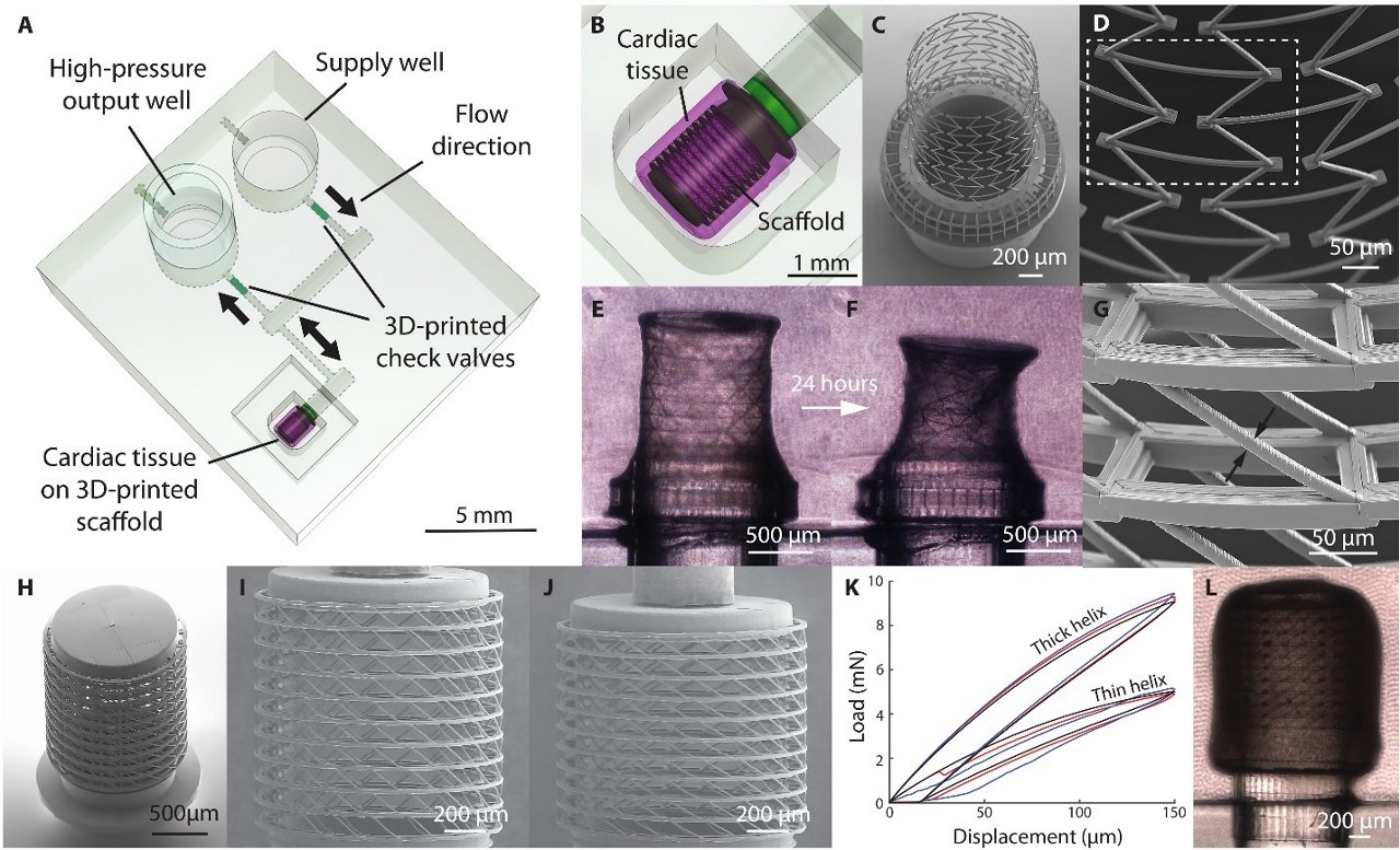
Miniaturized metamaterial scaffolds support contracting cardiac chambers
[/et_pb_text][/et_pb_column][/et_pb_row][/et_pb_section]